Product Description
Planetary Gearbox gear speed reducer motor track drive system reduction gearbox transmission epicyclic precision nema 34 wind turbine hollow shaft high torque
What is Planetary Gearbox?
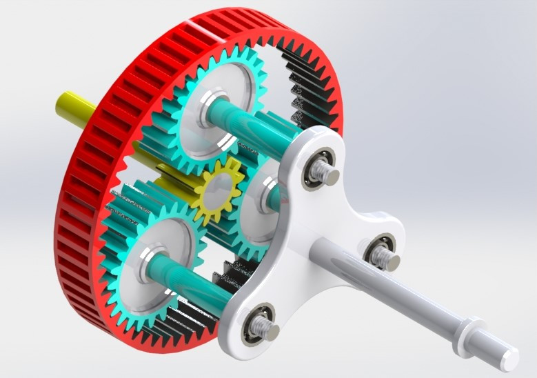
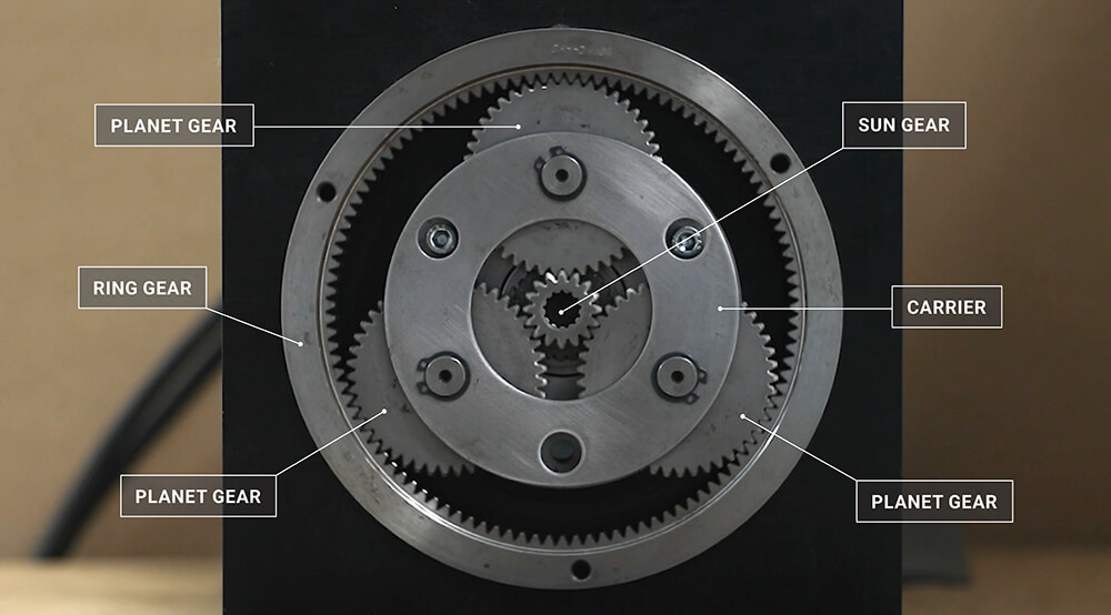
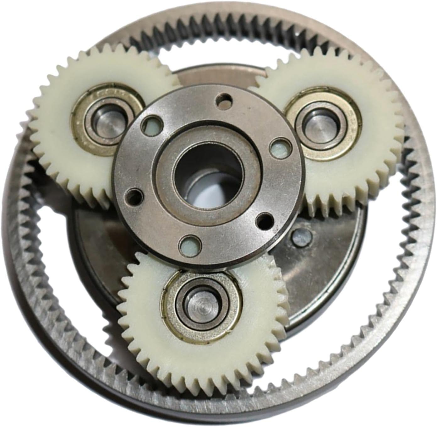
A planetary gearbox, also known as an epicyclic gearbox, is a gear unit commonly used in drive technologies. It consists of a central gear, called the sun gear, and a number of smaller gears, called planet gears, that orbit around the sun gear. The planet gears are held in place by a carrier, which can rotate independently of the sun gear. The ring gear is fixed in place and meshes with the planet gears.
The planetary gearbox can be used to transmit power from the input shaft to the output shaft. The gear ratio of the planetary gearbox is determined by the number of teeth on the sun gear, the number of teeth on each planet gear, and the number of planet gears.
Planetary gearboxes have a number of advantages over other types of gear reducers. They are compact, lightweight, and efficient. They can also handle high torque loads and have a wide range of gear ratios.
Planetary gearboxes are used in a wide variety of applications, including:
- Automatic transmissions
- Robotics
- CNC machines
- Electric vehicles
- Wind turbines
- Camera lenses
- Optical instruments
Here are some of the benefits of using planetary gearboxes:
- Compact size: Planetary gearboxes are very compact, making them ideal for use in applications where space is limited.
- Lightweight: Planetary gearboxes are also very lightweight, making them easy to transport and install.
- Efficiency: Planetary gearboxes are very efficient, with gear losses typically less than 1%.
- High torque capacity: Planetary gearboxes can handle high torque loads, making them ideal for use in applications such as electric vehicles and wind turbines.
- Wide range of gear ratios: Planetary gearboxes can be configured to provide a wide range of gear ratios, making them versatile and adaptable to a variety of applications.
Here are some of the limitations of using planetary gearboxes:
- Cost: Planetary gearboxes can be more expensive than other types of gear reducers.
- Noise: Planetary gearboxes can be noisy, especially at high speeds.
- Maintenance: Planetary gearboxes require regular maintenance to ensure that they operate properly.
| Application: | Motor, Electric Cars, Motorcycle, Machinery, Marine, Toy, Agricultural Machinery, Car |
|---|---|
| Function: | Distribution Power, Clutch, Change Drive Torque, Change Drive Direction, Speed Changing, Speed Reduction, Speed Increase |
| Layout: | Three-Ring |
| Hardness: | Hardened Tooth Surface |
| Installation: | Torque Arm Type |
| Step: | Stepless |
| Samples: |
US$ 9999/Piece
1 Piece(Min.Order) | |
|---|
What are the advantages of using epicyclic gears in automotive transmissions?
Epicyclic gears, also known as planetary gears, offer several advantages when used in automotive transmissions. Here’s a detailed explanation:
1. Compact Design:
Epicyclic gears provide a compact design, allowing automotive transmissions to be more space-efficient compared to other gear arrangements. This is particularly beneficial in modern vehicles where available space is limited. The compactness of epicyclic gears enables manufacturers to design smaller and lighter transmissions, resulting in overall weight reduction and improved vehicle fuel efficiency.
2. Gear Ratio Flexibility:
Epicyclic gears offer a wide range of gear ratios through the combination of the sun gear, planet gears, and ring gear. This flexibility allows automotive transmissions to provide multiple gear ratios, enabling smooth gear shifting and optimal engine performance across various driving conditions. Epicyclic gear systems can incorporate different gear sets and stages to achieve specific gear ratios, enhancing the vehicle’s acceleration, towing capabilities, and fuel economy.
3. Efficient Power Transmission:
The design of epicyclic gears facilitates efficient power transmission. The multiple planet gears distribute torque evenly across the gear system, minimizing power losses and improving overall transmission efficiency. This efficiency is particularly important in automotive transmissions, where efficient power transfer is vital for the vehicle’s performance and fuel economy.
4. Torque Multiplication and Gear Reduction:
Epicyclic gears can be configured to provide torque multiplication or gear reduction, depending on the arrangement of the gears. This capability is utilized in automotive transmissions to increase torque output during low-speed or high-load conditions, such as when starting from a standstill or climbing steep hills. Torque multiplication improves the vehicle’s drivability and towing capacity, enhancing its overall performance.
5. Smooth and Seamless Gear Shifts:
Epicyclic gears contribute to smooth and seamless gear shifts in automotive transmissions. The design allows for overlapping engagement of gears during gear shifting, minimizing the interruption of power delivery and providing a smoother transition between gears. This results in improved driving comfort and reduced wear on transmission components.
6. Durability and Reliability:
Epicyclic gears are known for their durability and reliability, making them well-suited for automotive applications. The design distributes load and wear among multiple planet gears, reducing stress on individual gear teeth and prolonging the lifespan of the transmission. Additionally, the compact and enclosed nature of the gear system provides protection against contaminants and external elements, further enhancing its reliability.
These advantages make epicyclic gears a popular choice in automotive transmissions, as they contribute to improved vehicle performance, fuel efficiency, and overall driving experience.
How do epicyclic gears contribute to reducing gear wear and noise?
Epicyclic gears, also known as planetary gears, offer several advantages that contribute to reducing gear wear and noise. Here’s a detailed explanation:
1. Load Distribution:
The arrangement of multiple planet gears in an epicyclic gear system helps distribute the load evenly across the gear teeth. This load distribution minimizes stress concentration on individual gear teeth, reducing the risk of wear and fatigue failure. By sharing the load, epicyclic gears can handle higher torque levels while reducing the wear on specific gear teeth.
2. Increased Tooth Contact Ratio:
Epicyclic gears typically have a higher tooth contact ratio compared to other gear types, such as spur or helical gears. The tooth contact ratio refers to the number of teeth in contact at any given time. A higher tooth contact ratio results in a smoother distribution of load and reduces localized contact stresses. This helps to minimize wear and noise generation during gear operation.
3. Balanced Loading:
The design of epicyclic gears allows for balanced loading of the gear teeth. The load is distributed among multiple planet gears, and each gear tooth engages with multiple teeth on both the sun gear and the ring gear simultaneously. This balanced loading helps to minimize tooth deflection and backlash, reducing wear and noise generation.
4. Lubrication:
Epicyclic gears benefit from effective lubrication due to their design. The gear teeth are constantly immersed in the lubricant, which helps reduce friction and wear. Proper lubrication also helps to dampen vibrations and reduce noise generated during gear operation.
5. Controlled Speed and Load Transitions:
Epicyclic gears can provide smooth speed and load transitions due to their ability to change gear ratios. When transitioning from one gear ratio to another, the gear engagement can be carefully controlled to minimize sudden shocks or impacts, which can contribute to wear and noise. The controlled speed and load transitions in epicyclic gears help reduce gear wear and noise levels.
6. Precision Manufacturing:
Epicyclic gears are often manufactured with high precision to ensure accurate gear meshing and minimize manufacturing errors. Precise gear manufacturing helps to maintain proper alignment and minimize tooth misalignment, which can lead to increased wear and noise.
In summary, the load distribution, increased tooth contact ratio, balanced loading, lubrication, controlled speed and load transitions, and precision manufacturing of epicyclic gears all contribute to reducing gear wear and noise. These factors make epicyclic gears a favorable choice in applications where minimizing wear and noise levels is important.
How does an epicyclic gear differ from other types of gears?
An epicyclic gear, also known as a planetary gear, exhibits several distinguishing features that set it apart from other types of gears. Here’s a detailed explanation of the differences:
1. Gear Arrangement:
An epicyclic gear system consists of a central sun gear, multiple planet gears, and an outer ring gear, also known as the annular gear. This arrangement differs from other gear types like spur gears, helical gears, or bevel gears, which typically involve meshing between two parallel or intersecting shafts.
2. Gear Motion:
The motion of an epicyclic gear system is characterized by the planet gears rotating while simultaneously orbiting around the sun gear. This combination of rotational and orbital motion is unique to epicyclic gears and allows them to achieve different gear ratios and functions.
3. Gear Ratios:
Epicyclic gears offer a wide range of gear ratios by varying the engagement of the sun gear, planet gears, and annular gear. This versatility in gear ratios is not typically found in other gear types, which often have fixed ratios determined by the number of teeth on the gears.
4. Compactness:
Epicyclic gears are known for their compact design. The arrangement of the gears allows for a relatively large gear reduction or multiplication within a compact space. This compactness makes them suitable for applications where space is limited, such as in automotive transmissions.
5. Functions and Applications:
Epicyclic gears offer various functions beyond basic speed reduction or increase. They can achieve torque multiplication, directional changes, and braking capabilities, providing versatility in mechanical systems. These unique functions make epicyclic gears well-suited for applications ranging from automatic transmissions and power tools to robotics and aerospace systems.
6. Complexity:
Compared to simpler gear types like spur gears, epicyclic gears can be more complex and require precise design and manufacturing. The interaction between the sun gear, planet gears, and annular gear involves multiple points of contact, requiring careful consideration of gear profiles, clearances, and alignment.
In summary, an epicyclic gear stands out from other types of gears due to its specific gear arrangement, motion characteristics, versatile gear ratios, compactness, unique functions, and complexity. Its ability to provide multiple gear ratios and perform various functions makes it a valuable choice in many mechanical systems.


editor by CX 2023-09-28
China wholesaler Pf/Wpf Series Epicyclic Gearbox spurs gear
Product Description
Product Description
high demand output customized cnc router gear box
Brief introduction:
*Theory
Gear box is used to transfer rotation and torque from motor to working machine,
*Function
the function is to decrease speed by gears and increase torque.
*Main specification
1. low backlash
2. high output torque-the industry’s highest torque density
3. balanced motor pinion
4. high efficiency(up to 98%)
5. ratio 3:1 to 1000:1
6. low noise
7. operable in any mounting positions
8. lifetime lubrication
Application
*Filed:
Be widely used for materials handing equipment, engineering machinery,metallurgy industry,mining industry,petrochemical industry, construction machinery,textile industry, medical apparatus and instruments, instrument and meter industry,automobile industry,marine industry,weapons industry, aerospace field,and so on.
*case:
| Golf trolley | Carton sealer | DC motor | Food machine | Printing machine | Stepper motor |
| AC motor | Conveying machine | Diesel | Foam machine | Packing machine | Servo motor |
| CNC | Crane machine | Dyeing machine | Lawn mower | Paper machine | Textile machine |
Our full production process strictly adhered to the ISO9001 quality control system, our higher quality , advanced equipment and technology ensure a guarantee in leakage-proof , retention and duration !
Your OEM orders are also warmly welcomed, it is our commitment to satisfy your requirement, please turst that we will be your reliable business partner for our good reputation,good quality and competitive price !
| Application: | Industry |
|---|---|
| Hardness: | Hardened |
| Type: | Circular Gear |
| Brand: | Lectstyle |
| Frame Size: | Pf40~Pf160 |
| Type Spec: | 40/60/80/120/140/160 |
| Customization: |
Available
| Customized Request |
|---|
What are the advantages of using epicyclic gears in automotive transmissions?
Epicyclic gears, also known as planetary gears, offer several advantages when used in automotive transmissions. Here’s a detailed explanation:
1. Compact Design:
Epicyclic gears provide a compact design, allowing automotive transmissions to be more space-efficient compared to other gear arrangements. This is particularly beneficial in modern vehicles where available space is limited. The compactness of epicyclic gears enables manufacturers to design smaller and lighter transmissions, resulting in overall weight reduction and improved vehicle fuel efficiency.
2. Gear Ratio Flexibility:
Epicyclic gears offer a wide range of gear ratios through the combination of the sun gear, planet gears, and ring gear. This flexibility allows automotive transmissions to provide multiple gear ratios, enabling smooth gear shifting and optimal engine performance across various driving conditions. Epicyclic gear systems can incorporate different gear sets and stages to achieve specific gear ratios, enhancing the vehicle’s acceleration, towing capabilities, and fuel economy.
3. Efficient Power Transmission:
The design of epicyclic gears facilitates efficient power transmission. The multiple planet gears distribute torque evenly across the gear system, minimizing power losses and improving overall transmission efficiency. This efficiency is particularly important in automotive transmissions, where efficient power transfer is vital for the vehicle’s performance and fuel economy.
4. Torque Multiplication and Gear Reduction:
Epicyclic gears can be configured to provide torque multiplication or gear reduction, depending on the arrangement of the gears. This capability is utilized in automotive transmissions to increase torque output during low-speed or high-load conditions, such as when starting from a standstill or climbing steep hills. Torque multiplication improves the vehicle’s drivability and towing capacity, enhancing its overall performance.
5. Smooth and Seamless Gear Shifts:
Epicyclic gears contribute to smooth and seamless gear shifts in automotive transmissions. The design allows for overlapping engagement of gears during gear shifting, minimizing the interruption of power delivery and providing a smoother transition between gears. This results in improved driving comfort and reduced wear on transmission components.
6. Durability and Reliability:
Epicyclic gears are known for their durability and reliability, making them well-suited for automotive applications. The design distributes load and wear among multiple planet gears, reducing stress on individual gear teeth and prolonging the lifespan of the transmission. Additionally, the compact and enclosed nature of the gear system provides protection against contaminants and external elements, further enhancing its reliability.
These advantages make epicyclic gears a popular choice in automotive transmissions, as they contribute to improved vehicle performance, fuel efficiency, and overall driving experience.
How do epicyclic gears offer compact solutions in space-constrained applications?
Epicyclic gears, also known as planetary gears, provide compact solutions in space-constrained applications. Here’s a detailed explanation:
1. Concentric Design:
Epicyclic gears have a concentric design where multiple gears are arranged around a central sun gear. This concentric arrangement allows for the transmission of torque and motion within a compact space. The gears share a common center, resulting in a smaller overall footprint compared to other gear systems.
2. Multiple Gear Stages:
Epicyclic gears can achieve multiple gear stages within a single gear system. By stacking planet gears and incorporating additional ring gears, the gear reduction or speed increase can be multiplied, all within a compact assembly. This eliminates the need for multiple separate gear systems, saving space and simplifying the mechanical layout.
3. High Gear Reduction:
Epicyclic gears offer high gear reduction capabilities. The arrangement of multiple planet gears allows for a high reduction ratio within a single stage of gears. This high gear reduction enables compact power transmission systems and is particularly useful in applications where space is limited, such as small robots or micro-actuators.
4. Inline Input and Output:
Epicyclic gears have an inline input and output configuration, where the input and output shafts are aligned on the same axis. This inline arrangement contributes to a more compact design, as it eliminates the need for additional space to redirect the motion or torque between non-aligned shafts.
5. Integration with Other Components:
Epicyclic gears can be easily integrated with other mechanical components, such as motors or actuators, within a compact space. The modular design of epicyclic gears allows for seamless integration, enabling the creation of more compact and efficient power transmission systems.
6. Customizable Gear Ratios:
Epicyclic gears offer flexibility in achieving customizable gear ratios. By varying the number of teeth on the gears or using different combinations of gears, specific gear ratios can be obtained to meet the requirements of the application. This customization capability allows for optimized space utilization and efficient power transmission.
7. Reduction of External Support Components:
Epicyclic gears can reduce the need for additional support components, such as idler gears or external shafts, which are often required in other gear systems. By incorporating multiple gears within a single assembly, epicyclic gears can achieve the desired motion and torque transfer without relying on external supporting structures, resulting in a more compact overall system.
In summary, epicyclic gears offer compact solutions in space-constrained applications through their concentric design, multiple gear stages, high gear reduction capabilities, inline input and output configuration, integration with other components, customizable gear ratios, and reduction of external support components. These features make epicyclic gears a preferred choice for achieving compact and efficient power transmission in various applications where space is limited.
“`
How does an epicyclic gear differ from other types of gears?
An epicyclic gear, also known as a planetary gear, exhibits several distinguishing features that set it apart from other types of gears. Here’s a detailed explanation of the differences:
1. Gear Arrangement:
An epicyclic gear system consists of a central sun gear, multiple planet gears, and an outer ring gear, also known as the annular gear. This arrangement differs from other gear types like spur gears, helical gears, or bevel gears, which typically involve meshing between two parallel or intersecting shafts.
2. Gear Motion:
The motion of an epicyclic gear system is characterized by the planet gears rotating while simultaneously orbiting around the sun gear. This combination of rotational and orbital motion is unique to epicyclic gears and allows them to achieve different gear ratios and functions.
3. Gear Ratios:
Epicyclic gears offer a wide range of gear ratios by varying the engagement of the sun gear, planet gears, and annular gear. This versatility in gear ratios is not typically found in other gear types, which often have fixed ratios determined by the number of teeth on the gears.
4. Compactness:
Epicyclic gears are known for their compact design. The arrangement of the gears allows for a relatively large gear reduction or multiplication within a compact space. This compactness makes them suitable for applications where space is limited, such as in automotive transmissions.
5. Functions and Applications:
Epicyclic gears offer various functions beyond basic speed reduction or increase. They can achieve torque multiplication, directional changes, and braking capabilities, providing versatility in mechanical systems. These unique functions make epicyclic gears well-suited for applications ranging from automatic transmissions and power tools to robotics and aerospace systems.
6. Complexity:
Compared to simpler gear types like spur gears, epicyclic gears can be more complex and require precise design and manufacturing. The interaction between the sun gear, planet gears, and annular gear involves multiple points of contact, requiring careful consideration of gear profiles, clearances, and alignment.
In summary, an epicyclic gear stands out from other types of gears due to its specific gear arrangement, motion characteristics, versatile gear ratios, compactness, unique functions, and complexity. Its ability to provide multiple gear ratios and perform various functions makes it a valuable choice in many mechanical systems.
editor by CX 2023-09-11
China wholesaler Powdered Metal Custom Press Sintered Planet Epicyclic Gear for Power Tool helical bevel gear
Product Description
OEM small module gears sintered gear
| Product Name | High precision gear manufacturers by powder metallurgy |
| Material | Iron powder, alloy powder,precious metal powder |
| Technology | Sintering – Powder Metallurgy |
| Certificate | ISO9001/TS16949 |
| Surface Treatment | High frequency quenching, oil impregnation,CNC,vacuum cleaning,polishing, |
| Apperance | No crumbling, cracks, exfoliation, voids, metal pitting and other defects |
| Process Flow |
Powder mixing – Forming – Sintering – Oil impregnation – Sizing -Ultrasonic cleaning – Steam oxidation – Oil impregnation – Final inspection – Packing |
| Application | Motorcycle parts, auto parts, Power Tools parts, Motor parts, electric Bicycle, |
Why Powdered metals?
Significant cost savings.
Create complex or unique shapes.
No or minimal waste during production.
High quality finished products.
Strength of materials
Production process of powder metallurgy
Powder mixing – Forming – Sintering – Oil impregnation – Sizing -Ultrasonic cleaning – Steam oxidation – Oil impregnation – Final inspection – Packing
Company Profile
JINGSHI established in 2007
Manufacturer & Exporter
Exacting in producing powder metallurgy gears and parts
Passed ISO/TS16949 Quality Certificate
Advanced Equipment
Numbers senior R & D engineers and Skilled operators
Precise Examination Instruments.
Strict Quality Control
With the “More diversity, More superior, More professional ” business purposes, we are committed to establish long-term friendship and CZPT relationship with domestic and international customers to create a bright future .
Certification
Please Send us your 2D or 3D drawings to start our cooperation!
| Pressing Speed: | Impact Forming |
|---|---|
| Suppression Method: | Bidirectional Pressurization |
| Application: | Mechanical Gadgets, Auto Parts, Electric Appliances, Medical Apparatus, Bag Accessories, Machiery Parts |
| Material: | Iron Powder |
| Hardness: | 50-75 |
| Density: | 6.4-7.4 g/cm3 |
| Samples: |
US$ 1/Piece
1 Piece(Min.Order) | |
|---|
| Customization: |
Available
| Customized Request |
|---|
How does an epicyclic gear mechanism work in automatic transmissions?
An epicyclic gear mechanism, also known as a planetary gear system, plays a crucial role in the operation of automatic transmissions. Here’s a detailed explanation:
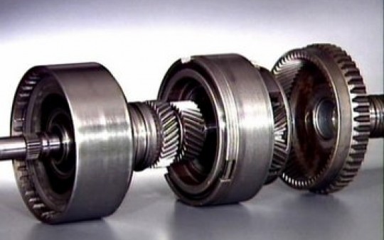
An automatic transmission utilizes a combination of different clutches, bands, and an epicyclic gear system to achieve gear ratios and control the transfer of power from the engine to the wheels. The epicyclic gear mechanism consists of the following components:
1. Sun Gear:
The sun gear is a central gear placed at the center of the mechanism. It receives power from the engine and is connected to the input shaft of the transmission.
2. Planet Gears:
Several planet gears are arranged around the sun gear and mesh with both the sun gear and the ring gear. The planet gears are mounted on a carrier, which allows them to rotate around the sun gear.
3. Ring Gear:
The ring gear is the outermost gear in the mechanism and has internal teeth that engage with the planet gears. The ring gear is connected to the output shaft, which transfers power to the wheels.
Here’s how the epicyclic gear mechanism works in an automatic transmission:
1. Neutral Position:
In the neutral position, no gears are engaged, and power flows freely through the transmission without any gear reduction or multiplication. The sun gear and the ring gear remain stationary.
2. Gear Engagement:
When a specific gear is selected, hydraulic clutches and bands are used to engage and disengage various elements of the epicyclic gear mechanism. The clutches and bands selectively hold and release specific gears to achieve the desired gear ratio.
3. Gear Ratios:
The gear ratio is determined by the arrangement and engagement of the gears in the epicyclic gear system. The sun gear, planet gears, and ring gear interact to produce different gear ratios. By selectively holding or releasing specific gears using clutches and bands, different gear ratios can be achieved, allowing the transmission to adapt to different driving conditions.
4. Power Flow:
The power flows through the different elements of the epicyclic gear mechanism based on the gear ratio selected. The input power from the engine is transmitted to the sun gear. Depending on the gear ratio, power is then transferred to the planet gears and the ring gear. The output shaft, connected to the ring gear, receives the power and transfers it to the wheels, propelling the vehicle.
5. Shifting Gears:
When shifting gears, the hydraulic control system of the transmission adjusts the engagement of the clutches and bands, causing the epicyclic gear mechanism to shift to a different gear ratio. This allows for seamless and automatic gear changes without the need for manual shifting.
Overall, the epicyclic gear mechanism in automatic transmissions enables the transmission to provide different gear ratios, control power flow, and facilitate smooth gear shifting. This mechanism plays a crucial role in the efficient and automatic operation of automatic transmissions in vehicles.
What is the effect of various planetary gear arrangements on gear ratios?
The arrangement of planetary gears in an epicyclic gear system can have different effects on the resulting gear ratios. Here’s a detailed explanation:
1. Simple Planetary Gear:
In a simple planetary gear arrangement, the sun gear is the input, the ring gear is the output, and the planet gears are held stationary or act as idlers. The gear ratio in this configuration is determined by the number of teeth on the sun gear and the ring gear. The gear ratio formula can be expressed as R = (1 + S) / S, where R is the gear ratio and S is the number of teeth on the sun gear.
2. Compound Planetary Gear:
A compound planetary gear arrangement includes multiple sets of planetary gears. This arrangement can achieve higher gear ratios by utilizing multiple gear stages. Each stage consists of a sun gear, planet gears, and a ring gear. The output of one stage becomes the input for the next stage, resulting in a cumulative gear ratio. The overall gear ratio is the product of the individual gear ratios of each stage.
3. Multi-Stage Planetary Gear:
A multi-stage planetary gear arrangement combines multiple simple or compound planetary gearsets in series. Each gearset has its own gear ratio, and the output of one gearset becomes the input for the next gearset. This arrangement allows for even higher gear ratios by multiplying the individual gear ratios of each gearset. The overall gear ratio is the product of the gear ratios of all the gearsets.
4. Ravigneaux Planetary Gear:
A Ravigneaux planetary gear arrangement consists of two sets of planetary gears, with one set acting as a compound gear. This arrangement allows for different gear ratios depending on the engagement of clutches or brakes. By selectively engaging or disengaging certain elements, different gear ratios can be achieved, providing versatility in speed control and gear reduction.
5. Simpson Planetary Gear:
A Simpson planetary gear arrangement consists of three sets of planetary gears. It offers multiple gear ratios by selectively engaging or disengaging clutches or brakes on different gear elements. This arrangement provides a range of gear ratios and allows for more flexibility in speed control and power transmission.
6. Hybrid Planetary Gear:
A hybrid planetary gear arrangement combines different types of planetary gearsets, such as compound, Ravigneaux, or Simpson. This arrangement offers a wide range of gear ratios and allows for more complex speed control and power transmission requirements.
In summary, the various planetary gear arrangements, including simple, compound, multi-stage, Ravigneaux, Simpson, and hybrid, have different effects on gear ratios. These arrangements enable the achievement of specific gear ratios, cumulative gear ratios, or a combination of different gear ratios, providing versatility in speed control, gear reduction, and power transmission in a wide range of applications.
What is the role of a sun gear, planet gears, and ring gear in an epicyclic arrangement?
In an epicyclic gear arrangement, the sun gear, planet gears, and ring gear each have specific roles and functions. Here’s a detailed explanation:
1. Sun Gear:
The sun gear is the central gear component in an epicyclic arrangement. Its primary role is to provide the input rotational motion or power to the gear system. The sun gear is typically located at the center and is surrounded by the planet gears. It engages with the planet gears through meshing teeth, transmitting rotational force to them.
2. Planet Gears:
The planet gears are multiple gears that revolve around the sun gear in an epicyclic arrangement. They are mounted on a carrier, which holds and supports the planet gears. The planet gears mesh with both the sun gear and the ring gear. As the sun gear rotates, it causes the planet gears to rotate around their own axes while simultaneously orbiting around the sun gear. The planet gears transmit the rotational motion and torque from the sun gear to the ring gear.
3. Ring Gear:
The ring gear, also known as the annular gear or the outer gear, is the outermost gear component in an epicyclic arrangement. It has internal teeth that mesh with the planet gears. The ring gear provides the outer boundary of the gear system and engages with the planet gears, transferring the rotational motion and torque from the planet gears to the output or the next stage of the gear system. In some arrangements, the ring gear is fixed or held stationary, while in others, it can rotate.
The combination and interaction of the sun gear, planet gears, and ring gear in an epicyclic arrangement enable various gear functions, such as gear reduction, torque multiplication, speed control, and directional changes. The arrangement and engagement of these gears determine the gear ratios and overall performance of the gear system.
editor by CX 2023-09-08
China Best Sales Planetary Gearbox Gear Speed Reducer Motor Track Drive System Reduction Gearbox Transmission Epicyclic Precision NEMA 34 Wind Turbine Hollow Shaft High Torque wholesaler
Product Description
Planetary Gearbox Gear Speed Reducer Motor Track Drive System Reduction Gearbox Transmission Epicyclic Precision NEMA 34 Wind Turbine Hollow Shaft High Torque
Application of Planetary Gearbox
Planetary gearboxes are a type of gear train that consists of a central sun gear, a ring gear, and a number of planet gears that mesh with both the sun gear and the ring gear. The planet gears are held in place by a carrier, which can rotate around the sun gear. The planetary gear train can be configured to provide a variety of gear ratios, depending on the number of planet gears and the relative sizes of the sun gear, ring gear, and carrier.
Planetary gearboxes are used in a wide variety of applications, including:
- Automotive: Planetary gearboxes are used in automotive transmissions to transmit power from the engine to the wheels. They are also used in power steering systems and differentials.
- Industrial machinery: Planetary gearboxes are used in a variety of industrial machines, such as conveyor belts, mixers, and pumps. They are also used in robotics and machine tools.
- Aerospace: Planetary gearboxes are used in aerospace applications, such as aircraft landing gear and satellite control systems.
- Photography: Planetary gearboxes are used in camera lenses to provide smooth and quiet focusing.
- Medical devices: Planetary gearboxes are used in a variety of medical devices, such as surgical robots and pacemakers.
Planetary gearboxes are a versatile and reliable type of gear train that can be used in a wide variety of applications. Their advantages over other types of gear trains include:
- Compact size: Planetary gearboxes are typically much smaller than other types of gear trains with the same gear ratio. This makes them ideal for applications where space is limited.
- High efficiency: Planetary gearboxes are very efficient, which means that they can transmit more power with less energy loss.
- Smooth operation: Planetary gearboxes operate smoothly and quietly, which makes them ideal for applications where noise is a concern.
- Long life: Planetary gearboxes are very durable and can withstand a wide range of operating conditions. This makes them ideal for applications where reliability is critical.
| Application: | Motor, Electric Cars, Motorcycle, Machinery, Marine, Toy, Agricultural Machinery, Car |
|---|---|
| Function: | Distribution Power, Clutch, Change Drive Torque, Change Drive Direction, Speed Changing, Speed Reduction, Speed Increase |
| Layout: | Three-Ring |
| Hardness: | Hardened Tooth Surface |
| Installation: | Torque Arm Type |
| Step: | Stepless |
| Samples: |
US$ 9999/Piece
1 Piece(Min.Order) | |
|---|
How do epicyclic gears contribute to gear reduction and speed increase?
Epicyclic gears, also known as planetary gears, play a significant role in achieving gear reduction and speed increase in various mechanical systems. Here’s a detailed explanation:
1. Gear Reduction:
Epicyclic gears can achieve gear reduction by utilizing their unique gear arrangement. The gear reduction is achieved by fixing or holding certain components of the gear system, such as the ring gear or the planet carrier, while the input and output shafts rotate. This causes the sun gear to drive the planet gears, resulting in a reduction of output speed and an increase in torque. The gear ratio formula for gear reduction in an epicyclic gear system is R = (1 + S) / (1 + R), where R is the number of teeth on the ring gear and S is the number of teeth on the sun gear.
2. Speed Increase:
Epicyclic gears can also be used to achieve speed increase when certain components of the gear system are held fixed or driven while the output shaft rotates. In this configuration, the input torque is divided among multiple planet gears, which rotate around the sun gear and drive the output shaft. This results in an increase in output speed and a decrease in torque. The gear ratio formula for speed increase in an epicyclic gear system is R = (1 + R) / (1 + S), where R is the number of teeth on the ring gear and S is the number of teeth on the sun gear.
3. Multiple Stages:
Epicyclic gears can achieve higher gear reduction or speed increase by incorporating multiple stages within a single gear system. Each stage consists of a set of gears, including a sun gear, planet gears, and a ring gear. The output of one stage becomes the input for the next stage, allowing for a cumulative effect on the gear ratio. By stacking multiple stages, the overall gear reduction or speed increase can be multiplied, providing a wide range of gear ratios to suit different application requirements.
4. Customizable Gear Ratios:
Epicyclic gears offer flexibility in achieving customizable gear ratios. By varying the number of teeth on the gears or using different combinations of gears, specific gear ratios can be obtained to meet the needs of the application. This customization capability allows for optimized speed control, gear reduction, and torque multiplication, making epicyclic gears versatile in a wide range of mechanical systems.
5. Compact Design:
Epicyclic gears contribute to gear reduction and speed increase while maintaining a compact design. The concentric arrangement of gears and the ability to achieve multiple gear stages within a single gear system result in a smaller overall footprint compared to other gear arrangements. This compact design is particularly useful in space-constrained applications where achieving high gear reduction or speed increase is essential.
In summary, epicyclic gears contribute to gear reduction and speed increase through their unique gear arrangement, multiple stages, customizable gear ratios, and compact design. These features make them widely used in various mechanical systems, such as automotive transmissions, industrial machinery, and robotics, where efficient power transmission and speed control are crucial.
How do epicyclic gears contribute to reducing gear wear and noise?
Epicyclic gears, also known as planetary gears, offer several advantages that contribute to reducing gear wear and noise. Here’s a detailed explanation:
1. Load Distribution:
The arrangement of multiple planet gears in an epicyclic gear system helps distribute the load evenly across the gear teeth. This load distribution minimizes stress concentration on individual gear teeth, reducing the risk of wear and fatigue failure. By sharing the load, epicyclic gears can handle higher torque levels while reducing the wear on specific gear teeth.
2. Increased Tooth Contact Ratio:
Epicyclic gears typically have a higher tooth contact ratio compared to other gear types, such as spur or helical gears. The tooth contact ratio refers to the number of teeth in contact at any given time. A higher tooth contact ratio results in a smoother distribution of load and reduces localized contact stresses. This helps to minimize wear and noise generation during gear operation.
3. Balanced Loading:
The design of epicyclic gears allows for balanced loading of the gear teeth. The load is distributed among multiple planet gears, and each gear tooth engages with multiple teeth on both the sun gear and the ring gear simultaneously. This balanced loading helps to minimize tooth deflection and backlash, reducing wear and noise generation.
4. Lubrication:
Epicyclic gears benefit from effective lubrication due to their design. The gear teeth are constantly immersed in the lubricant, which helps reduce friction and wear. Proper lubrication also helps to dampen vibrations and reduce noise generated during gear operation.
5. Controlled Speed and Load Transitions:
Epicyclic gears can provide smooth speed and load transitions due to their ability to change gear ratios. When transitioning from one gear ratio to another, the gear engagement can be carefully controlled to minimize sudden shocks or impacts, which can contribute to wear and noise. The controlled speed and load transitions in epicyclic gears help reduce gear wear and noise levels.
6. Precision Manufacturing:
Epicyclic gears are often manufactured with high precision to ensure accurate gear meshing and minimize manufacturing errors. Precise gear manufacturing helps to maintain proper alignment and minimize tooth misalignment, which can lead to increased wear and noise.
In summary, the load distribution, increased tooth contact ratio, balanced loading, lubrication, controlled speed and load transitions, and precision manufacturing of epicyclic gears all contribute to reducing gear wear and noise. These factors make epicyclic gears a favorable choice in applications where minimizing wear and noise levels is important.
What are the applications of epicyclic gears in various industries?
Epicyclic gears, also known as planetary gears, have a wide range of applications across various industries. Here’s a detailed explanation of their applications:
1. Automotive Industry:
Epicyclic gears are extensively used in automotive transmissions. They provide multiple gear ratios, allowing vehicles to efficiently transfer power from the engine to the wheels at different speeds. Automatic transmissions, dual-clutch transmissions, and continuously variable transmissions (CVT) often employ epicyclic gear systems to achieve smooth gear shifts, improved fuel efficiency, and enhanced performance.
2. Robotics and Automation:
Epicyclic gears play a crucial role in robotic systems and automation equipment. They are used in robotic joints and manipulators to control movements and transmit torque. The compact size, high torque capacity, and versatility of epicyclic gears make them ideal for precise and efficient motion control in robotics.
3. Aerospace Industry:
Epicyclic gears find applications in the aerospace industry, particularly in aircraft engines and auxiliary systems. They are used in gearboxes to transmit power from the engine to various components, such as generators, pumps, and auxiliary systems. Epicyclic gears are preferred for their compactness, high torque capacity, and ability to achieve multiple gear ratios.
4. Power Tools:
Epicyclic gears are widely employed in power tools such as drills, impact drivers, and wrenches. They provide the necessary torque multiplication and speed reduction to deliver high power output. Epicyclic gears enable power tools to efficiently transfer and control rotational motion, enhancing their performance and usability.
5. Industrial Machinery:
Epicyclic gears are used in various industrial machinery and equipment. They find applications in conveyors, printing machines, textile machinery, packaging equipment, and more. Epicyclic gears enable speed control, torque multiplication, and directional changes, facilitating the efficient operation of industrial processes.
6. Renewable Energy:
Epicyclic gears are utilized in wind turbines and solar tracking systems. They help optimize the rotational speed of wind turbine blades and enable solar panels to track the movement of the sun. Epicyclic gears contribute to efficient power generation in renewable energy systems.
7. Medical Devices:
Epicyclic gears have applications in medical devices and equipment such as surgical robots, imaging systems, and prosthetic devices. They enable precise and controlled movements, ensuring accurate diagnostics, surgical procedures, and rehabilitation.
These are just a few examples of the diverse applications of epicyclic gears. Their ability to provide multiple gear ratios, compactness, high torque capacity, and versatility make them indispensable in a wide range of industries where efficient power transmission and motion control are essential.
editor by CX 2023-09-07
China Custom Epicyclic Spur Transmission Planetary Sun Gear top gear
Product Description
Product Description
Product Parameters
| Item | Spur Gear Axle Shaft |
| Material | 4140,4340,40Cr,42Crmo,42Crmo4,20Cr,20CrMnti, 20Crmo,35Crmo |
| OEM NO | Customize |
| Certification | ISO/TS16949 |
| Test Requirement | Magnetic Powder Test, Hardness Test, Dimension Test |
| Color | Paint , Natural Finish ,Machining All Around |
| Material | Aluminum: 5000series(5052…)/6000series(6061…)/7000series(7075…) |
| Steel: Carbon Steel,Middle Steel,Steel Alloy,etc. | |
| Stainess Steel: 303/304/316,etc. | |
| Copper/Brass/Bronze/Red Copper,etc. | |
| Plastic:ABS,PP,PC,Nylon,Delrin(POM),Bakelite,etc. | |
| Size | According to Customer’s drawing or samples |
| Process | CNC machining,Turning,Milling,Stamping,Grinding,Welding,Wire Injection,Cutting,etc. |
| Tolerance | ≥+/-0.03mm |
| Surface Treatment | (Sandblast)&(Hard)&(Color)Anodizing,(Chrome,Nickel,Zinc…)Plating,Painting,Powder Coating,Polishing,Blackened,Hardened,Lasering,Engraving,etc. |
| File Formats | ProE,SolidWorks,UG,CAD,PDF(IGS,X-T,STP,STL) |
| Sample | Available |
| Packing | Spline protect cover ,Wood box ,Waterproof membrane; Or per customers’ requirements. |
Our Advantages
Why Choose US ???
1. Equipment :
Our company boasts all necessary production equipment,
including Hydraulic press machines, Japanese CNC lathe (TAKISAWA), Korean gear hobbing machine (I SNT), gear shaping machine, machining center, CNC grinder, heat treatment line etc.
2. Processing precision:
We are a professional gear & gear shafts manufacturer. Our gears are around 6-7 grade in mass production.
3. Company:
We have 90 employees, including 10 technical staffs. Covering an area of 20000 square meters.
4. Certification :
Oue company has passed ISO 14001 and TS16949
5.Sample service :
We provide free sample for confirmation and customer bears the freight charges
6.OEM service :
Having our own factory and professional technicians,we welcome OEM orders as well.We can design and produce the specific product you need according to your detail information
Cooperation Partner
Company Profile
Our Featured Products
| Application: | Motor, Electric Cars, Motorcycle, Machinery, Marine, Agricultural Machinery, Car |
|---|---|
| Manufacturing Method: | Cast Gear |
| Toothed Portion Shape: | Spur Gear |
| Material: | Stainless Steel |
| Type: | Circular Gear |
| Yield: | 5, 000PCS / Month |
| Samples: |
US$ 0/Piece
1 Piece(Min.Order) | |
|---|
| Customization: |
Available
| Customized Request |
|---|
How do epicyclic gears contribute to gear reduction and speed increase?
Epicyclic gears, also known as planetary gears, play a significant role in achieving gear reduction and speed increase in various mechanical systems. Here’s a detailed explanation:
1. Gear Reduction:
Epicyclic gears can achieve gear reduction by utilizing their unique gear arrangement. The gear reduction is achieved by fixing or holding certain components of the gear system, such as the ring gear or the planet carrier, while the input and output shafts rotate. This causes the sun gear to drive the planet gears, resulting in a reduction of output speed and an increase in torque. The gear ratio formula for gear reduction in an epicyclic gear system is R = (1 + S) / (1 + R), where R is the number of teeth on the ring gear and S is the number of teeth on the sun gear.
2. Speed Increase:
Epicyclic gears can also be used to achieve speed increase when certain components of the gear system are held fixed or driven while the output shaft rotates. In this configuration, the input torque is divided among multiple planet gears, which rotate around the sun gear and drive the output shaft. This results in an increase in output speed and a decrease in torque. The gear ratio formula for speed increase in an epicyclic gear system is R = (1 + R) / (1 + S), where R is the number of teeth on the ring gear and S is the number of teeth on the sun gear.
3. Multiple Stages:
Epicyclic gears can achieve higher gear reduction or speed increase by incorporating multiple stages within a single gear system. Each stage consists of a set of gears, including a sun gear, planet gears, and a ring gear. The output of one stage becomes the input for the next stage, allowing for a cumulative effect on the gear ratio. By stacking multiple stages, the overall gear reduction or speed increase can be multiplied, providing a wide range of gear ratios to suit different application requirements.
4. Customizable Gear Ratios:
Epicyclic gears offer flexibility in achieving customizable gear ratios. By varying the number of teeth on the gears or using different combinations of gears, specific gear ratios can be obtained to meet the needs of the application. This customization capability allows for optimized speed control, gear reduction, and torque multiplication, making epicyclic gears versatile in a wide range of mechanical systems.
5. Compact Design:
Epicyclic gears contribute to gear reduction and speed increase while maintaining a compact design. The concentric arrangement of gears and the ability to achieve multiple gear stages within a single gear system result in a smaller overall footprint compared to other gear arrangements. This compact design is particularly useful in space-constrained applications where achieving high gear reduction or speed increase is essential.
In summary, epicyclic gears contribute to gear reduction and speed increase through their unique gear arrangement, multiple stages, customizable gear ratios, and compact design. These features make them widely used in various mechanical systems, such as automotive transmissions, industrial machinery, and robotics, where efficient power transmission and speed control are crucial.
How do epicyclic gears contribute to reducing gear wear and noise?
Epicyclic gears, also known as planetary gears, offer several advantages that contribute to reducing gear wear and noise. Here’s a detailed explanation:
1. Load Distribution:
The arrangement of multiple planet gears in an epicyclic gear system helps distribute the load evenly across the gear teeth. This load distribution minimizes stress concentration on individual gear teeth, reducing the risk of wear and fatigue failure. By sharing the load, epicyclic gears can handle higher torque levels while reducing the wear on specific gear teeth.
2. Increased Tooth Contact Ratio:
Epicyclic gears typically have a higher tooth contact ratio compared to other gear types, such as spur or helical gears. The tooth contact ratio refers to the number of teeth in contact at any given time. A higher tooth contact ratio results in a smoother distribution of load and reduces localized contact stresses. This helps to minimize wear and noise generation during gear operation.
3. Balanced Loading:
The design of epicyclic gears allows for balanced loading of the gear teeth. The load is distributed among multiple planet gears, and each gear tooth engages with multiple teeth on both the sun gear and the ring gear simultaneously. This balanced loading helps to minimize tooth deflection and backlash, reducing wear and noise generation.
4. Lubrication:
Epicyclic gears benefit from effective lubrication due to their design. The gear teeth are constantly immersed in the lubricant, which helps reduce friction and wear. Proper lubrication also helps to dampen vibrations and reduce noise generated during gear operation.
5. Controlled Speed and Load Transitions:
Epicyclic gears can provide smooth speed and load transitions due to their ability to change gear ratios. When transitioning from one gear ratio to another, the gear engagement can be carefully controlled to minimize sudden shocks or impacts, which can contribute to wear and noise. The controlled speed and load transitions in epicyclic gears help reduce gear wear and noise levels.
6. Precision Manufacturing:
Epicyclic gears are often manufactured with high precision to ensure accurate gear meshing and minimize manufacturing errors. Precise gear manufacturing helps to maintain proper alignment and minimize tooth misalignment, which can lead to increased wear and noise.
In summary, the load distribution, increased tooth contact ratio, balanced loading, lubrication, controlled speed and load transitions, and precision manufacturing of epicyclic gears all contribute to reducing gear wear and noise. These factors make epicyclic gears a favorable choice in applications where minimizing wear and noise levels is important.
What are the applications of epicyclic gears in various industries?
Epicyclic gears, also known as planetary gears, have a wide range of applications across various industries. Here’s a detailed explanation of their applications:
1. Automotive Industry:
Epicyclic gears are extensively used in automotive transmissions. They provide multiple gear ratios, allowing vehicles to efficiently transfer power from the engine to the wheels at different speeds. Automatic transmissions, dual-clutch transmissions, and continuously variable transmissions (CVT) often employ epicyclic gear systems to achieve smooth gear shifts, improved fuel efficiency, and enhanced performance.
2. Robotics and Automation:
Epicyclic gears play a crucial role in robotic systems and automation equipment. They are used in robotic joints and manipulators to control movements and transmit torque. The compact size, high torque capacity, and versatility of epicyclic gears make them ideal for precise and efficient motion control in robotics.
3. Aerospace Industry:
Epicyclic gears find applications in the aerospace industry, particularly in aircraft engines and auxiliary systems. They are used in gearboxes to transmit power from the engine to various components, such as generators, pumps, and auxiliary systems. Epicyclic gears are preferred for their compactness, high torque capacity, and ability to achieve multiple gear ratios.
4. Power Tools:
Epicyclic gears are widely employed in power tools such as drills, impact drivers, and wrenches. They provide the necessary torque multiplication and speed reduction to deliver high power output. Epicyclic gears enable power tools to efficiently transfer and control rotational motion, enhancing their performance and usability.
5. Industrial Machinery:
Epicyclic gears are used in various industrial machinery and equipment. They find applications in conveyors, printing machines, textile machinery, packaging equipment, and more. Epicyclic gears enable speed control, torque multiplication, and directional changes, facilitating the efficient operation of industrial processes.
6. Renewable Energy:
Epicyclic gears are utilized in wind turbines and solar tracking systems. They help optimize the rotational speed of wind turbine blades and enable solar panels to track the movement of the sun. Epicyclic gears contribute to efficient power generation in renewable energy systems.
7. Medical Devices:
Epicyclic gears have applications in medical devices and equipment such as surgical robots, imaging systems, and prosthetic devices. They enable precise and controlled movements, ensuring accurate diagnostics, surgical procedures, and rehabilitation.
These are just a few examples of the diverse applications of epicyclic gears. Their ability to provide multiple gear ratios, compactness, high torque capacity, and versatility make them indispensable in a wide range of industries where efficient power transmission and motion control are essential.
editor by CX 2023-09-06
China OEM Custom Manufacturer Carbon Steel spiral bevel gear set steel pinion worm spur gears gear cycle
Condition: New
Warranty: 3 months
Shape: BEVEL
Applicable Industries: Manufacturing Plant, Machinery Repair Shops, Farms, Retail, Construction works , Energy & Mining
Weight (KG): 1
Showroom Location: None
Video outgoing-inspection: Provided
Machinery Test Report: Provided
Marketing Type: Ordinary Product
Warranty of core components: Not Available
Core Components: PLC, Engine, Bearing, Gearbox, Motor, Pressure vessel, Gear, Pump
Tooth Profile: HELICAL GEAR
Direction: Right Hand
Material: Steel, Steel, Hip Hop New 4mm Copper Inlaid Transparent Pink Aquamarine Zircon Row Necklace Tennis Chain carbon steel
Processing: Forging
Standard or Nonstandard: Nonstandard, Accept OEM Orders
Outer Diameter: Customized
Product Name: Carbon steel spiral bevel gear
Teeth: Hardened
Heat treatment: Hardening and Tempering
Surface treatment: Painting, Blacken, Zinc plate
Usage: Machinery Parts
Keywords: gear
Dimensions: Clients
Quality: 100% Inspection
Packaging Details: Export standard packing.
Port: ZheJiang Port
PRODUCT DETAILS
| 1 | Name | Precision gear |
| 2 | Size | Products can be customized. |
| 3 | Manufacture Standard | 5-8 Grade ISO1328-1997. |
| 4 | Material | 45#Steel,20CrMnTi,40Cr,20CrNiMo,20MnCr5,GCR15SiMn,42CrMo,2Cr13stainless steel,Nylon,Bakelite,Copper, Sale All Kinds Track Roller Carrier Roller Sprocket Front idler Track Shoe Track Link Excavator Undercarriage Spare Parts Aluminium.etc |
| 5 | Production Process | The main process is Gear Hobbing, Gear Shaping and Gear Grinding, Selecting production process according to the differentproducts. |
| 6 | Heat Treatment | Carburizing and quenching ,High-frequency quenching,Nitriding, Hardening and tempering, Selecting heat treatment according to thedifferent materials. |
| 7 | Testing Equipment | Rockwell hardness tester 500RA, Double mesh instrument HD-200B & 3102,Gear measurement center instrument CNC3906T other High precision detection equipments |
| 8 | Certification | GB/T19001-2016/ISO9001:2015 |
| 9 | Usage | Used in printing machine, cleaning machine, medical equipment, garden machine, construction machine, PDD FOR SAAB 9000 9-2 -93 ATV UTV CV AXLE DRIVE SHAFT electric car, valve,forklift, transportation equipment and various gear reducers.etc |
| 10 | Package | According to customer’s request |

How to Design a Forging Spur Gear
Before you start designing your own spur gear, you need to understand its main components. Among them are Forging, Keyway, Spline, Set screw and other types. Understanding the differences between these types of spur gears is essential for making an informed decision. To learn more, keep reading. Also, don’t hesitate to contact me for assistance! Listed below are some helpful tips and tricks to design a spur gear. Hopefully, they will help you design the spur gear of your dreams.
Forging spur gears
Forging spur gears is one of the most important processes of automotive transmission components. The manufacturing process is complex and involves several steps, such as blank spheroidizing, hot forging, annealing, phosphating, and saponification. The material used for spur gears is typically 20CrMnTi. The process is completed by applying a continuous through extrusion forming method with dies designed for the sizing band length L and Splitting angle thickness T.
The process of forging spur gears can also use polyacetal (POM), a strong plastic commonly used for the manufacture of gears. This material is easy to mold and shape, and after hardening, it is extremely stiff and abrasion resistant. A number of metals and alloys are used for spur gears, including forged steel, stainless steel, and aluminum. Listed below are the different types of materials used in gear manufacturing and their advantages and disadvantages.
A spur gear’s tooth size is measured in modules, or m. Each number represents the number of teeth in the gear. As the number of teeth increases, so does its size. In general, the higher the number of teeth, the larger the module is. A high module gear has a large pressure angle. It’s also important to remember that spur gears must have the same module as the gears they are used to drive.
Set screw spur gears
A modern industry cannot function without set screw spur gears. These gears are highly efficient and are widely used in a variety of applications. Their design involves the calculation of speed and torque, which are both critical factors. The MEP model, for instance, considers the changing rigidity of a tooth pair along its path. The results are used to determine the type of spur gear required. Listed below are some tips for choosing a spur gear:
Type A. This type of gear does not have a hub. The gear itself is flat with a small hole in the middle. Set screw gears are most commonly used for lightweight applications without loads. The metal thickness can range from 0.25 mm to 3 mm. Set screw gears are also used for large machines that need to be strong and durable. This article provides an introduction to the different types of spur gears and how they differ from one another.
Pin Hub. Pin hub spur gears use a set screw to secure the pin. These gears are often connected to a shaft by dowel, spring, or roll pins. The pin is drilled to the precise diameter to fit inside the gear, so that it does not come loose. Pin hub spur gears have high tolerances, as the hole is not large enough to completely grip the shaft. This type of gear is generally the most expensive of the three.
Keyway spur gears
In today’s modern industry, spur gear transmissions are widely used to transfer power. These types of transmissions provide excellent efficiency but can be susceptible to power losses. These losses must be estimated during the design process. A key component of this analysis is the calculation of the contact area (2b) of the gear pair. However, this value is not necessarily applicable to every spur gear. Here are some examples of how to calculate this area. (See Figure 2)
Spur gears are characterized by having teeth parallel to the shafts and axis, and a pitch line velocity of up to 25 m/s is considered high. In addition, they are more efficient than helical gears of the same size. Unlike helical gears, spur gears are generally considered positive gears. They are often used for applications in which noise control is not an issue. The symmetry of the spur gear makes them especially suitable for applications where a constant speed is required.
Besides using a helical spur gear for the transmission, the gear can also have a standard tooth shape. Unlike helical gears, spur gears with an involute tooth form have thick roots, which prevents wear from the teeth. These gears are easily made with conventional production tools. The involute shape is an ideal choice for small-scale production and is one of the most popular types of spur gears.
Spline spur gears
When considering the types of spur gears that are used, it’s important to note the differences between the two. A spur gear, also called an involute gear, generates torque and regulates speed. It’s most common in car engines, but is also used in everyday appliances. However, one of the most significant drawbacks of spur gears is their noise. Because spur gears mesh only one tooth at a time, they create a high amount of stress and noise, making them unsuitable for everyday use.
The contact stress distribution chart represents the flank area of each gear tooth and the distance in both the axial and profile direction. A high contact area is located toward the center of the gear, which is caused by the micro-geometry of the gear. A positive l value indicates that there is no misalignment of the spline teeth on the interface with the helix hand. The opposite is true for negative l values.
Using an upper bound technique, Abdul and Dean studied the forging of spur gear forms. They assumed that the tooth profile would be a straight line. They also examined the non-dimensional forging pressure of a spline. Spline spur gears are commonly used in motors, gearboxes, and drills. The strength of spur gears and splines is primarily dependent on their radii and tooth diameter.
SUS303 and SUS304 stainless steel spur gears
Stainless steel spur gears are manufactured using different techniques, which depend on the material and the application. The most common process used in manufacturing them is cutting. Other processes involve rolling, casting, and forging. In addition, plastic spur gears are produced by injection molding, depending on the quantity of production required. SUS303 and SUS304 stainless steel spur gears can be made using a variety of materials, including structural carbon steel S45C, gray cast iron FC200, nonferrous metal C3604, engineering plastic MC901, and stainless steel.
The differences between 304 and 303 stainless steel spur gears lie in their composition. The two types of stainless steel share a common design, but have varying chemical compositions. China and Japan use the letters SUS304 and SUS303, which refer to their varying degrees of composition. As with most types of stainless steel, the two different grades are made to be used in industrial applications, such as planetary gears and spur gears.
Stainless steel spur gears
There are several things to look for in a stainless steel spur gear, including the diametral pitch, the number of teeth per unit diameter, and the angular velocity of the teeth. All of these aspects are critical to the performance of a spur gear, and the proper dimensional measurements are essential to the design and functionality of a spur gear. Those in the industry should be familiar with the terms used to describe spur gear parts, both to ensure clarity in production and in purchase orders.
A spur gear is a type of precision cylindrical gear with parallel teeth arranged in a rim. It is used in various applications, such as outboard motors, winches, construction equipment, lawn and garden equipment, turbine drives, pumps, centrifuges, and a variety of other machines. A spur gear is typically made from stainless steel and has a high level of durability. It is the most commonly used type of gear.
Stainless steel spur gears can come in many different shapes and sizes. Stainless steel spur gears are generally made of SUS304 or SUS303 stainless steel, which are used for their higher machinability. These gears are then heat-treated with nitriding or tooth surface induction. Unlike conventional gears, which need tooth grinding after heat-treating, stainless steel spur gears have a low wear rate and high machinability.
editor by Cx 2023-07-13
China Best Sales 28t Trailer Parts Landing Gear Single or Double helical bevel gear
Product Description
Product Parameters
| Landing Gear | |||
| Landng Gear model | Type of landing gear foot | Lift stroke | Mounting height |
| KM280001A | A | 430mm | 814mm |
| KM280002A | A | 480mm | 864mm |
| KM280001R | R | 430mm | 797mm |
| KM280002R | R | 480mm | 820mm |
| KM280001G | G | 430mm | 770mm |
| KM280002G | G | 480mm | 847mm |
| KM280001S | S | 430mm | 822mm |
| KM280002S | S | 480mm | 872mm |
| KM280001T | T | 430mm | 794mm |
| KM280002T | T | 480mm | 844mm |
Product Description
We can produce as your requests.
Our company can supply various types of wheel bolts are used for trailers.
Customized is available.
Customer also can send us your specifications or drawings you need.
Certification: ISO9001: 2000 / TS16949
High quality and best price.
We are factory, not trading company.
Packaging & Shipping
FAQ
Q1:Are you a factory?
A:Yes,we are a factory,but not just a factory,as we have sales team,our own offices,and they
all can help the buyers and cooperative partners to decide which products are the best choices
for them,and all your requirements and inquires will be replyed in time.
Q2:What’s your Delivery Time?
A:In general, the delivery time is 15-20 days.We will make the delivery as soon as possible with
the guaranted quality.
Q3:What is the convenient way to pay?
A:L/C , T/T,Unionpay,DP are accepted,and if you have a better idea , please be free sharing with us.
Q4:Which type of shipping would be better?
A:Generally,in consideration of the cheap and safe superiorities of sea transportation,we advice
to make delivery by sea.What’s more, we respect your views of other transportation as well.
| Type: | Landing Gear |
|---|---|
| Certification: | ISO/Ts16949, ISO, SGS |
| Loading Weight: | 25T |
| ABS: | Without ABS |
| Tent Type: | Simple |
| Axle Number: | None |
| Customization: |
Available
| Customized Request |
|---|
How to Design a Forging Spur Gear
Before you start designing your own spur gear, you need to understand its main components. Among them are Forging, Keyway, Spline, Set screw and other types. Understanding the differences between these types of spur gears is essential for making an informed decision. To learn more, keep reading. Also, don’t hesitate to contact me for assistance! Listed below are some helpful tips and tricks to design a spur gear. Hopefully, they will help you design the spur gear of your dreams.
Forging spur gears
Forging spur gears is one of the most important processes of automotive transmission components. The manufacturing process is complex and involves several steps, such as blank spheroidizing, hot forging, annealing, phosphating, and saponification. The material used for spur gears is typically 20CrMnTi. The process is completed by applying a continuous through extrusion forming method with dies designed for the sizing band length L and Splitting angle thickness T.
The process of forging spur gears can also use polyacetal (POM), a strong plastic commonly used for the manufacture of gears. This material is easy to mold and shape, and after hardening, it is extremely stiff and abrasion resistant. A number of metals and alloys are used for spur gears, including forged steel, stainless steel, and aluminum. Listed below are the different types of materials used in gear manufacturing and their advantages and disadvantages.
A spur gear’s tooth size is measured in modules, or m. Each number represents the number of teeth in the gear. As the number of teeth increases, so does its size. In general, the higher the number of teeth, the larger the module is. A high module gear has a large pressure angle. It’s also important to remember that spur gears must have the same module as the gears they are used to drive.
Set screw spur gears
A modern industry cannot function without set screw spur gears. These gears are highly efficient and are widely used in a variety of applications. Their design involves the calculation of speed and torque, which are both critical factors. The MEP model, for instance, considers the changing rigidity of a tooth pair along its path. The results are used to determine the type of spur gear required. Listed below are some tips for choosing a spur gear:
Type A. This type of gear does not have a hub. The gear itself is flat with a small hole in the middle. Set screw gears are most commonly used for lightweight applications without loads. The metal thickness can range from 0.25 mm to 3 mm. Set screw gears are also used for large machines that need to be strong and durable. This article provides an introduction to the different types of spur gears and how they differ from one another.
Pin Hub. Pin hub spur gears use a set screw to secure the pin. These gears are often connected to a shaft by dowel, spring, or roll pins. The pin is drilled to the precise diameter to fit inside the gear, so that it does not come loose. Pin hub spur gears have high tolerances, as the hole is not large enough to completely grip the shaft. This type of gear is generally the most expensive of the three.
Keyway spur gears
In today’s modern industry, spur gear transmissions are widely used to transfer power. These types of transmissions provide excellent efficiency but can be susceptible to power losses. These losses must be estimated during the design process. A key component of this analysis is the calculation of the contact area (2b) of the gear pair. However, this value is not necessarily applicable to every spur gear. Here are some examples of how to calculate this area. (See Figure 2)
Spur gears are characterized by having teeth parallel to the shafts and axis, and a pitch line velocity of up to 25 m/s is considered high. In addition, they are more efficient than helical gears of the same size. Unlike helical gears, spur gears are generally considered positive gears. They are often used for applications in which noise control is not an issue. The symmetry of the spur gear makes them especially suitable for applications where a constant speed is required.
Besides using a helical spur gear for the transmission, the gear can also have a standard tooth shape. Unlike helical gears, spur gears with an involute tooth form have thick roots, which prevents wear from the teeth. These gears are easily made with conventional production tools. The involute shape is an ideal choice for small-scale production and is one of the most popular types of spur gears.
Spline spur gears
When considering the types of spur gears that are used, it’s important to note the differences between the two. A spur gear, also called an involute gear, generates torque and regulates speed. It’s most common in car engines, but is also used in everyday appliances. However, one of the most significant drawbacks of spur gears is their noise. Because spur gears mesh only one tooth at a time, they create a high amount of stress and noise, making them unsuitable for everyday use.
The contact stress distribution chart represents the flank area of each gear tooth and the distance in both the axial and profile direction. A high contact area is located toward the center of the gear, which is caused by the micro-geometry of the gear. A positive l value indicates that there is no misalignment of the spline teeth on the interface with the helix hand. The opposite is true for negative l values.
Using an upper bound technique, Abdul and Dean studied the forging of spur gear forms. They assumed that the tooth profile would be a straight line. They also examined the non-dimensional forging pressure of a spline. Spline spur gears are commonly used in motors, gearboxes, and drills. The strength of spur gears and splines is primarily dependent on their radii and tooth diameter.
SUS303 and SUS304 stainless steel spur gears
Stainless steel spur gears are manufactured using different techniques, which depend on the material and the application. The most common process used in manufacturing them is cutting. Other processes involve rolling, casting, and forging. In addition, plastic spur gears are produced by injection molding, depending on the quantity of production required. SUS303 and SUS304 stainless steel spur gears can be made using a variety of materials, including structural carbon steel S45C, gray cast iron FC200, nonferrous metal C3604, engineering plastic MC901, and stainless steel.
The differences between 304 and 303 stainless steel spur gears lie in their composition. The two types of stainless steel share a common design, but have varying chemical compositions. China and Japan use the letters SUS304 and SUS303, which refer to their varying degrees of composition. As with most types of stainless steel, the two different grades are made to be used in industrial applications, such as planetary gears and spur gears.
Stainless steel spur gears
There are several things to look for in a stainless steel spur gear, including the diametral pitch, the number of teeth per unit diameter, and the angular velocity of the teeth. All of these aspects are critical to the performance of a spur gear, and the proper dimensional measurements are essential to the design and functionality of a spur gear. Those in the industry should be familiar with the terms used to describe spur gear parts, both to ensure clarity in production and in purchase orders.
A spur gear is a type of precision cylindrical gear with parallel teeth arranged in a rim. It is used in various applications, such as outboard motors, winches, construction equipment, lawn and garden equipment, turbine drives, pumps, centrifuges, and a variety of other machines. A spur gear is typically made from stainless steel and has a high level of durability. It is the most commonly used type of gear.
Stainless steel spur gears can come in many different shapes and sizes. Stainless steel spur gears are generally made of SUS304 or SUS303 stainless steel, which are used for their higher machinability. These gears are then heat-treated with nitriding or tooth surface induction. Unlike conventional gears, which need tooth grinding after heat-treating, stainless steel spur gears have a low wear rate and high machinability.
editor by CX 2023-07-13
China OEM European Pulley Spb280-2-2517 /SPA/Spb /Spc /Spz bevel gearbox
Product Description
Product Description
Product Parameters
| product | European standard pulley SPB280-2-2517 |
| material | stainless steel , iron , aluminum ,bronze ,carbon steel ,brass etc . |
| size | ISO standard ,customer requirements |
| BORE | Finished bore, Pilot Bore, Special request |
| surface treatment | Carburizing and Quenching,Tempering ,Tooth suface high quenching Hardening,Tempering |
| Processing Method | Molding, Shaving, Hobbing, Drilling, Tapping, Reaming, Manual Chamfering, Grinding etc |
| Heat Treatment | Quenching & Tempering, Carburizing & Quenching, High-frequency Hardening, Carbonitriding…… |
| Package | Wooden Case/Container and pallet, or made-to-order |
| Certificate | ISO9001 ,SGS |
| Machining Process | Gear Hobbing, Gear Milling, Gear Shaping, Gear Broaching, Gear Shaving, Gear Grinding and Gear Lapping |
| Applications | Toy, Automotive, instrument, electrical equipment, household appliances, furniture, mechanical equipment,daily living equipment, electronic sports equipment, , sanitation machinery, market/ hotel equipment supplies, etc. |
| Testing Equipment | Rockwell hardness tester 500RA, Double mesh instrument HD-200B & 3102,Gear measurement center instrument CNC3906T and other High precision detection equipments |
workshop & equipment
Production process
Certifications
Our Advantages
1 . Prioritized Quality
2 .Integrity-based Management
3 .Service Orientation
4 .150+ advanced equipment
5 .10000+ square meter factory area
6 .200+ outstanding employees
7 .90% employees have more than 10 year- working experience in our factory
8 .36 technical staff
9 .certificate ISO 9001 , SGS
10 . Customization support
11 .Excellent after-sales service
shipping
sample orders delivery time:
10-15 working days as usual
15-20 working days in busy season
large order leading time :
20-30 working days as usual
30-40 working days in busy season
FAQ
1. why should you buy products from us not from other suppliers?
We are a 32 year-experience manufacturer on making the gear, specializing in manufacturing varieties of gears, such as helical gear ,bevel gear ,spur gear and grinding gear, gear shaft, timing pulley, rack, , timing pulley and other transmission parts . There are 150+ advanced equipment ,200+ excellent employees ,and 36 technical staff . what’s more ,we have got ISO9001 and SGS certificate .
2: What are the common types of tooth profiles for synchronous belt pulleys?
A: The most common tooth profiles for synchronous belt pulleys are the trapezoidal (or T-type) and curvilinear (or HTD-type) profiles. The tooth profile determines the pitch diameter, which affects the overall ratio of the gear drive.
3 .How long is the delivery?
A: Small orders usually takes 10-15 working days,big order usually 20-35 days, depending on orders quantity and whether are standard size.
| Certification: | ISO |
|---|---|
| Pulley Sizes: | V-Belt |
| Manufacturing Process: | Forging |
| Material: | Stainless Steel |
| Surface Treatment: | Electroplating |
| Application: | Chemical Industry, Grain Transport, Mining Transport, Power Plant |
| Samples: |
US$ 5/Piece
1 Piece(Min.Order) | |
|---|
| Customization: |
Available
| Customized Request |
|---|

The Difference Between Planetary Gears and Spur Gears
A spur gear is a type of mechanical drive that turns an external shaft. The angular velocity is proportional to the rpm and can be easily calculated from the gear ratio. However, to properly calculate angular velocity, it is necessary to know the number of teeth. Fortunately, there are several different types of spur gears. Here’s an overview of their main features. This article also discusses planetary gears, which are smaller, more robust, and more power-dense.
Planetary gears are a type of spur gear
One of the most significant differences between planetary gears and spurgears is the way that the two share the load. Planetary gears are much more efficient than spurgears, enabling high torque transfer in a small space. This is because planetary gears have multiple teeth instead of just one. They are also suitable for intermittent and constant operation. This article will cover some of the main benefits of planetary gears and their differences from spurgears.
While spur gears are more simple than planetary gears, they do have some key differences. In addition to being more basic, they do not require any special cuts or angles. Moreover, the tooth shape of spur gears is much more complex than those of planetary gears. The design determines where the teeth make contact and how much power is available. However, a planetary gear system will be more efficient if the teeth are lubricated internally.
In a planetary gear, there are three shafts: a sun gear, a planet carrier, and an external ring gear. A planetary gear is designed to allow the motion of one shaft to be arrested, while the other two work simultaneously. In addition to two-shaft operation, planetary gears can also be used in three-shaft operations, which are called temporary three-shaft operations. Temporary three-shaft operations are possible through frictional coupling.
Among the many benefits of planetary gears is their adaptability. As the load is shared between several planet gears, it is easier to switch gear ratios, so you do not need to purchase a new gearbox for every new application. Another major benefit of planetary gears is that they are highly resistant to high shock loads and demanding conditions. This means that they are used in many industries.
They are more robust
An epicyclic gear train is a type of transmission that uses concentric axes for input and output. This type of transmission is often used in vehicles with automatic transmissions, such as a Lamborghini Gallardo. It is also used in hybrid cars. These types of transmissions are also more robust than conventional planetary gears. However, they require more assembly time than a conventional parallel shaft gear.
An epicyclic gearing system has three basic components: an input, an output, and a carrier. The number of teeth in each gear determines the ratio of input rotation to output rotation. In some cases, an epicyclic gear system can be made with two planets. A third planet, known as the carrier, meshes with the second planet and the sun gear to provide reversibility. A ring gear is made of several components, and a planetary gear may contain many gears.
An epicyclic gear train can be built so that the planet gear rolls inside the pitch circle of an outer fixed gear ring, or “annular gear.” In such a case, the curve of the planet’s pitch circle is called a hypocycloid. When epicycle gear trains are used in combination with a sun gear, the planetary gear train is made up of both types. The sun gear is usually fixed, while the ring gear is driven.
Planetary gearing, also known as epicyclic gear, is more durable than other types of transmissions. Because planets are evenly distributed around the sun, they have an even distribution of gears. Because they are more robust, they can handle higher torques, reductions, and overhung loads. They are also more energy-dense and robust. In addition, planetary gearing is often able to be converted to various ratios.
They are more power dense
The planet gear and ring gear of a compound planetary transmission are epicyclic stages. One part of the planet gear meshes with the sun gear, while the other part of the gear drives the ring gear. Coast tooth flanks are used only when the gear drive works in reversed load direction. Asymmetry factor optimization equalizes the contact stress safety factors of a planetary gear. The permissible contact stress, sHPd, and the maximum operating contact stress (sHPc) are equalized by asymmetry factor optimization.
In addition, epicyclic gears are generally smaller and require fewer space than helical ones. They are commonly used as differential gears in speed frames and in looms, where they act as a Roper positive let off. They differ in the amount of overdrive and undergearing ratio they possess. The overdrive ratio varies from fifteen percent to forty percent. In contrast, the undergearing ratio ranges from 0.87:1 to 69%.
The TV7-117S turboprop engine gearbox is the first known application of epicyclic gears with asymmetric teeth. This gearbox was developed by the CZPT Corporation for the Ilyushin Il-114 turboprop plane. The TV7-117S’s gearbox arrangement consists of a first planetary-differential stage with three planet gears and a second solar-type coaxial stage with five planet gears. This arrangement gives epicyclic gears the highest power density.
Planetary gearing is more robust and power-dense than other types of gearing. They can withstand higher torques, reductions, and overhung loads. Their unique self-aligning properties also make them highly versatile in rugged applications. It is also more compact and lightweight. In addition to this, epicyclic gears are easier to manufacture than planetary gears. And as a bonus, they are much less expensive.
They are smaller
Epicyclic gears are small mechanical devices that have a central “sun” gear and one or more outer intermediate gears. These gears are held in a carrier or ring gear and have multiple mesh considerations. The system can be sized and speeded by dividing the required ratio by the number of teeth per gear. This process is known as gearing and is used in many types of gearing systems.
Planetary gears are also known as epicyclic gearing. They have input and output shafts that are coaxially arranged. Each planet contains a gear wheel that meshes with the sun gear. These gears are small and easy to manufacture. Another advantage of epicyclic gears is their robust design. They are easily converted into different ratios. They are also highly efficient. In addition, planetary gear trains can be designed to operate in multiple directions.
Another advantage of epicyclic gearing is their reduced size. They are often used for small-scale applications. The lower cost is associated with the reduced manufacturing time. Epicyclic gears should not be made on N/C milling machines. The epicyclic carrier should be cast and tooled on a single-purpose machine, which has several cutters cutting through material. The epicyclic carrier is smaller than the epicyclic gear.
Epicyclic gearing systems consist of three basic components: an input, an output, and a stationary component. The number of teeth in each gear determines the ratio of input rotation to output rotation. Typically, these gear sets are made of three separate pieces: the input gear, the output gear, and the stationary component. Depending on the size of the input and output gear, the ratio between the two components is greater than half.
They have higher gear ratios
The differences between epicyclic gears and regular, non-epicyclic gears are significant for many different applications. In particular, epicyclic gears have higher gear ratios. The reason behind this is that epicyclic gears require multiple mesh considerations. The epicyclic gears are designed to calculate the number of load application cycles per unit time. The sun gear, for example, is +1300 RPM. The planet gear, on the other hand, is +1700 RPM. The ring gear is also +1400 RPM, as determined by the number of teeth in each gear.
Torque is the twisting force of a gear, and the bigger the gear, the higher the torque. However, since the torque is also proportional to the size of the gear, bigger radii result in lower torque. In addition, smaller radii do not move cars faster, so the higher gear ratios do not move at highway speeds. The tradeoff between speed and torque is the gear ratio.
Planetary gears use multiple mechanisms to increase the gear ratio. Those using epicyclic gears have multiple gear sets, including a sun, a ring, and two planets. Moreover, the planetary gears are based on helical, bevel, and spur gears. In general, the higher gear ratios of epicyclic gears are superior to those of planetary gears.
Another example of planetary gears is the compound planet. This gear design has two different-sized gears on either end of a common casting. The large end engages the sun while the smaller end engages the annulus. The compound planets are sometimes necessary to achieve smaller steps in gear ratio. As with any gear, the correct alignment of planet pins is essential for proper operation. If the planets are not aligned properly, it may result in rough running or premature breakdown.
editor by CX 2023-07-12
China manufacturer Custom Precision M1.5Z16 Small Steel Bevel Gear with Best Sales
Condition: New
Warranty: 6 Months
Shape: BEVEL
Applicable Industries: Electricity Tool
Weight (KG): 0.3
Showroom Location: None
Video outgoing-inspection: Provided
Machinery Test Report: Provided
Marketing Type: New Product 2571
Warranty of core components: 6 Months
Core Components: Gear
Tooth Profile: bevel
Material: Steel
Processing: Hobbing
Pressure Angle: 20 Degree
Standard or Nonstandard: Nonstandard
Outer Diameter: custom
Module(M): 1.5
Teeth(Z): 16
Case hardening: carburizing
Hardness: 55-60 HRC
Ratio: 16/17
Pressure angle: 20°
After Warranty Service: Online support
Packaging Details: Standard export package or custom per customer’s request
Port: ZheJiang or HangZhou
Products Description
| Specification | ||
| Precision grade | ISO grade 8 | |
| Pressure angle | 20° | |
| Material | SCM415, 15CrMo, 9310,8620 | |
| Heat treatment | Carburizing | |
| Tooth hardness | 59±2 HRC, 1.2~1.5 mm | |
| Surface treatment | light oiled | |
| Module | No. of teeth | Direction of spiral | Bore (AH7) | Pitch dia. (C) | Outside Dia. (D) | Face width (J) | Mounting distance (E) | Total length (F) | |||||||||||||||||||||||||||||||||||||||||||||||||||||||||||||||||||||||||
| 2 | 40 | right | 15 | 80 | 81.1 | 14 | 45 | 31.78 | |||||||||||||||||||||||||||||||||||||||||||||||||||||||||||||||||||||||||
| 2 | 20 | left | 12 | 40 | 44.1 | 14 | 55 | 28.16 | |||||||||||||||||||||||||||||||||||||||||||||||||||||||||||||||||||||||||
| 2.5 | 40 | right | 16 | 1-7281 6Q0820808B 6Q0820808F for Volkswagen Polo high Precision,low noise High Precision Power Transmission Gears for Machine Tools Non-orthogonal Spiral Bevel Gears Precision Gears for UAV Involute Spline Gears Gears for Industrial Robot Production Process Raw Material Rough Cutting Gear Turning Quenching & Tempering Gear Milling Heat Treatment Gear Grinding Testing Testing Gleason 1500GMM Inspection CenterDiameter: 1500Max Weight:4.5t Links CNC3906 Inspection CenterDiameter: 600 Automatic Inspection Line How Do Our Technical And Quality Team Support Our Clients And Partners? Our english speaking engineers do not simply relay messages. We help both customers and partners to strive for real solutions and we practise Kaizen in every single work. Quality Warranty : 12 months counting from the delivery of the goods. Product packaging Inner Package Carton Non-solid Wood Packing Iron box packing To be packed in new strong case(s)/carton(s), suitable for long distance ocean/air and inland transportation. In addition,we are willing to customize packaging per your request. Certifications ISO 9001 certification ISO/TS 16949 certification Main Application Fields Over 15 years accumulating, SMM gears are used in various industries in numerous machines. The main application fieldsincluding,but not limited to machine tools,UAV,Tobacco machinery,new energy automobile, TS1C clamp type bellows coupling flexible shaft connector servo motor high torque excellent response power transmission electical tools,cement vertical mill,oil drilling machine.SMM have been working with some global leading companies more than 10 years. Why Choose Us Being proactive, we constantly recognize and strive for opportunities that are beneficial to customers and self-improvement;Action speaks louder than words, we make fast decisions on the needs of customers, suppliers and employees. We are Ready to Support Your Further Success! ——SMM TEAM
Synthesis of Epicyclic Gear Trains for Automotive Automatic TransmissionsIn this article, we will discuss the synthesis of epicyclic gear trains for automotive automatic transmissions, their applications, and cost. After you have finished reading, you may want to do some research on the technology yourself. Here are some links to further reading on this topic. They also include an application in hybrid vehicle transmissions. Let’s look at the basic concepts of epicyclic gear trains. They are highly efficient and are a promising alternative to conventional gearing systems. Synthesis of epicyclic gear trains for automotive automatic transmissionsThe main purpose of automotive automatic transmissions is to maintain engine-drive wheel balance. The kinematic structure of epicyclic gear trains (EGTs) is derived from graph representations of these gear trains. The synthesis process is based on an algorithm that generates admissible epicyclic gear trains with up to ten links. This algorithm enables designers to design auto gear trains that have higher performance and better engine-drive wheel balance. ApplicationsThe epicyclic gear system is a type of planetary gear train. It can achieve a great speed reduction in a small space. In cars, epicyclic gear trains are often used for the automatic transmission. These gear trains are also useful in hoists and pulley blocks. They have many applications in both mechanical and electrical engineering. They can be used for high-speed transmission and require less space than other types of gear trains. CostThe cost of epicyclic gearing is lower when they are tooled rather than manufactured on a normal N/C milling machine. The epicyclic carriers should be manufactured in a casting and tooled using a single-purpose machine that has multiple cutters to cut the material simultaneously. This approach is widely used for industrial applications and is particularly useful in the automotive sector. The benefits of a well-made epicyclic gear transmission are numerous.
China Standard ZD Auto-induction Voltage-reduced Starting Cast Iron Material AC Torque Gear Motor gear ratio calculatorProduct Description
Model Selection ZD Leader has a wide range of micro motor production lines in the industry, including DC Motor, AC Motor, Brushless Motor, Planetary Gear Motor, Drum Motor, Planetary Gearbox, RV Reducer and Harmonic Gearbox etc. Through technical innovation and customization, we help you create outstanding application systems and provide flexible solutions for various industrial automation situations.
• Model Selection • Drawing Request If you need more product parameters, catalogues, CAD or 3D drawings, please contact us. • On Your Need We can modify standard products or customize them to meet your specific needs.
Detailed Photos Product Parameters Features: 2) Reduction ration: SPECIFICATION FOR AC MOTORS:
Other Related Products Click here to find what you are looking for: Company Profile
FAQ Q: What’re your main products? Q: How to select a suitable motor? Q: Do you have a customized service for your standard motors? Q: Do you have an individual design service for motors? Q: What’s your lead time?
Spiral Gears for Right-Angle Right-Hand DrivesSpiral gears are used in mechanical systems to transmit torque. The bevel gear is a particular type of spiral gear. It is made up of two gears that mesh with one another. Both gears are connected by a bearing. The two gears must be in mesh alignment so that the negative thrust will push them together. If axial play occurs in the bearing, the mesh will have no backlash. Moreover, the design of the spiral gear is based on geometrical tooth forms. Equations for spiral gearThe theory of divergence requires that the pitch cone radii of the pinion and gear be skewed in different directions. This is done by increasing the slope of the convex surface of the gear’s tooth and decreasing the slope of the concave surface of the pinion’s tooth. The pinion is a ring-shaped wheel with a central bore and a plurality of transverse axes that are offset from the axis of the spiral teeth. Design of spiral bevel gearsA proposed design of spiral bevel gears utilizes a function-to-form mapping method to determine the tooth surface geometry. This solid model is then tested with a surface deviation method to determine whether it is accurate. Compared to other right-angle gear types, spiral bevel gears are more efficient and compact. CZPT Gear Company gears comply with AGMA standards. A higher quality spiral bevel gear set achieves 99% efficiency. Limitations to geometrically obtained tooth formsThe geometrically obtained tooth forms of a spiral gear can be calculated from a nonlinear programming problem. The tooth approach Z is the linear displacement error along the contact normal. It can be calculated using the formula given in Eq. (23) with a few additional parameters. However, the result is not accurate for small loads because the signal-to-noise ratio of the strain signal is small.
| |||||||||||||||||||||||||||||||||||||||||||||||||||||||||||||||||||||||||||||


